I made a numpad to experiment with the firmware and check I understand the full process for building a keyboard, before committing to the PCB design for the split keyboard. As it is only a prototype, it is rough around the edges (mostly in the case design).
Physical design
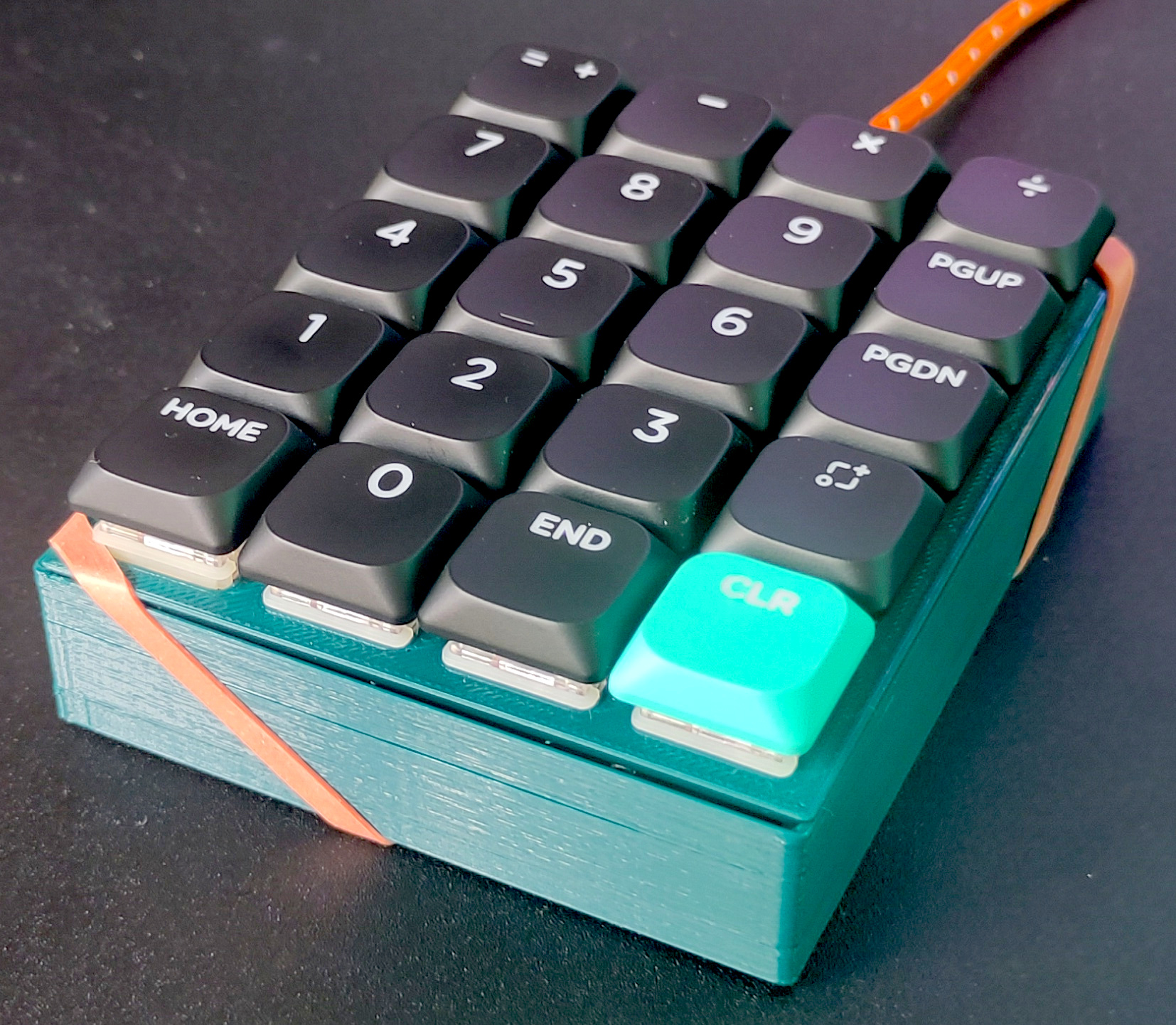
I 3D printed the case. The spacing between keys on the initial print was slightly to tight, but it worked the second time.
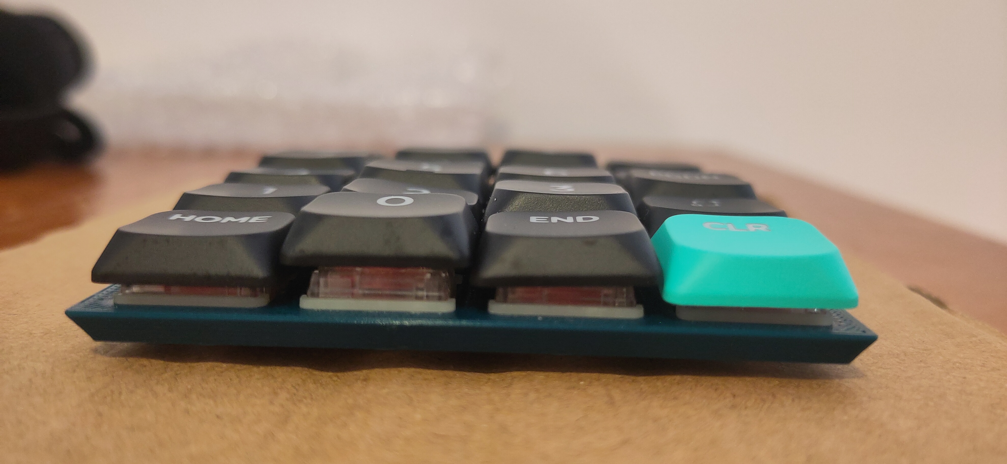
For now the case is just held together by an elastic band because I want to move on the keyboard design.
Electronic design
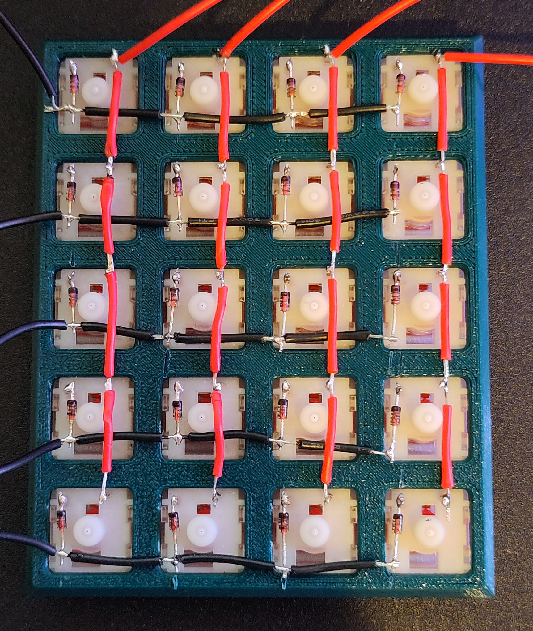
The keys are arranged in a 4x5 matrix, such that each key can be identified by raising the voltage on one column and checking to see if any rows match the raised voltage. A diode it added to each key to prevent current flowing from one row to the next if multiple keys are pressed, causing keys to registered incorrectly.
Firmware
I planned on using KMK firmware on a Pico 2W. KMK is quite easy to get started with, just defining which pins the rows and columns are connected to and function of each key. However, after much debugging I discovered that the rp2350 on the Pico 2 has a bug preventing the use of the pull down resistors on the GPIO pins. I switched back to an original Pico, as I had one spare and it was the cleanest solution, and suddenly everything worked perfectly.
Outcomes
I won’t be using a Pico 2W for my keyboard. I have ordered some Seeed Studio XIAO nRF52840s, as they are what are what are used in this keyboard build and should have a very low power draw if I decide to make the keyboard wireless.
KMK is nice and easy to use. I will give QMK and ZMK a test as well, but I know I shouldn’t have major firmware issues on the keyboard now.
I may potentially convert the numpad into a macropad at some point.