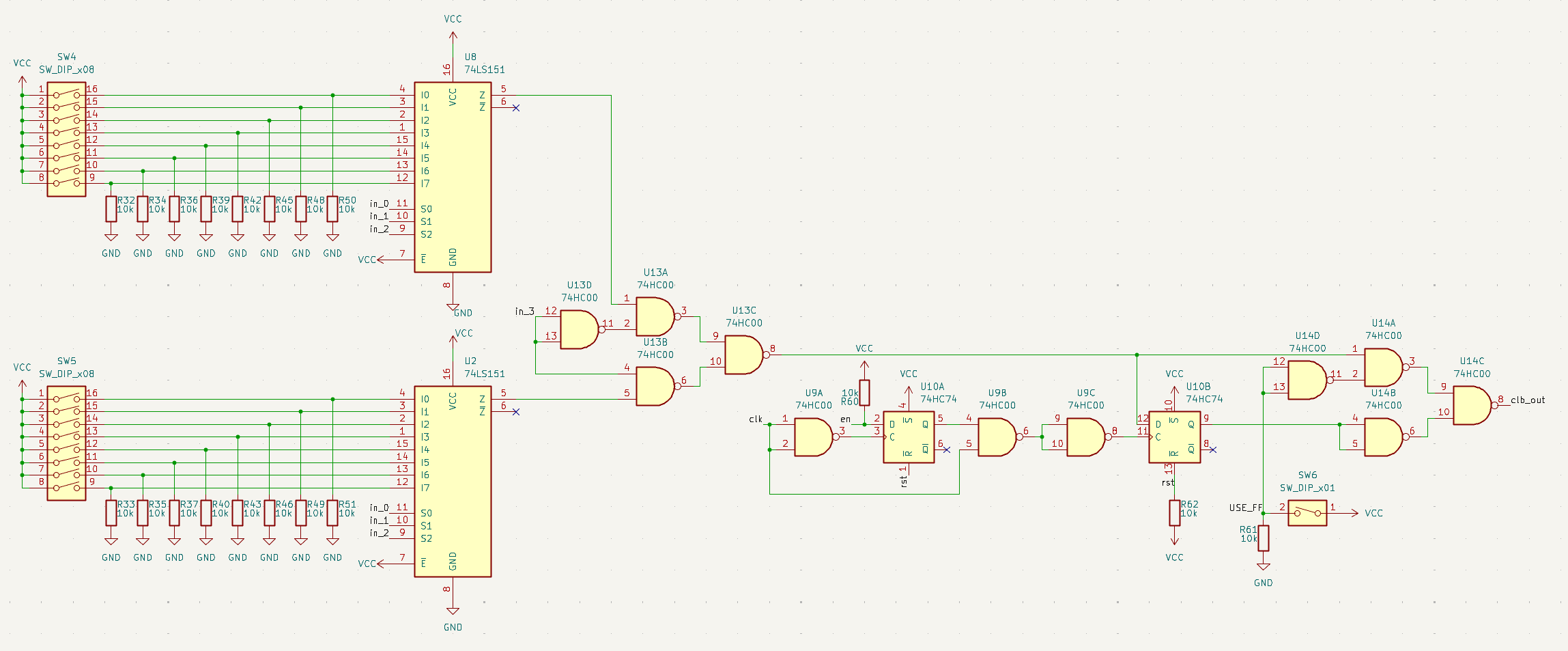
The Configurable Logic Block (CLB) has a 4 input/1 output Look Up Table (LUT). The output can be passed though a flip flop, based on the configuration switches. This means that any synchronous or asynchronous 4 input boolean logic function can be implemented in hardware without changing any of the components.
Look Up Table
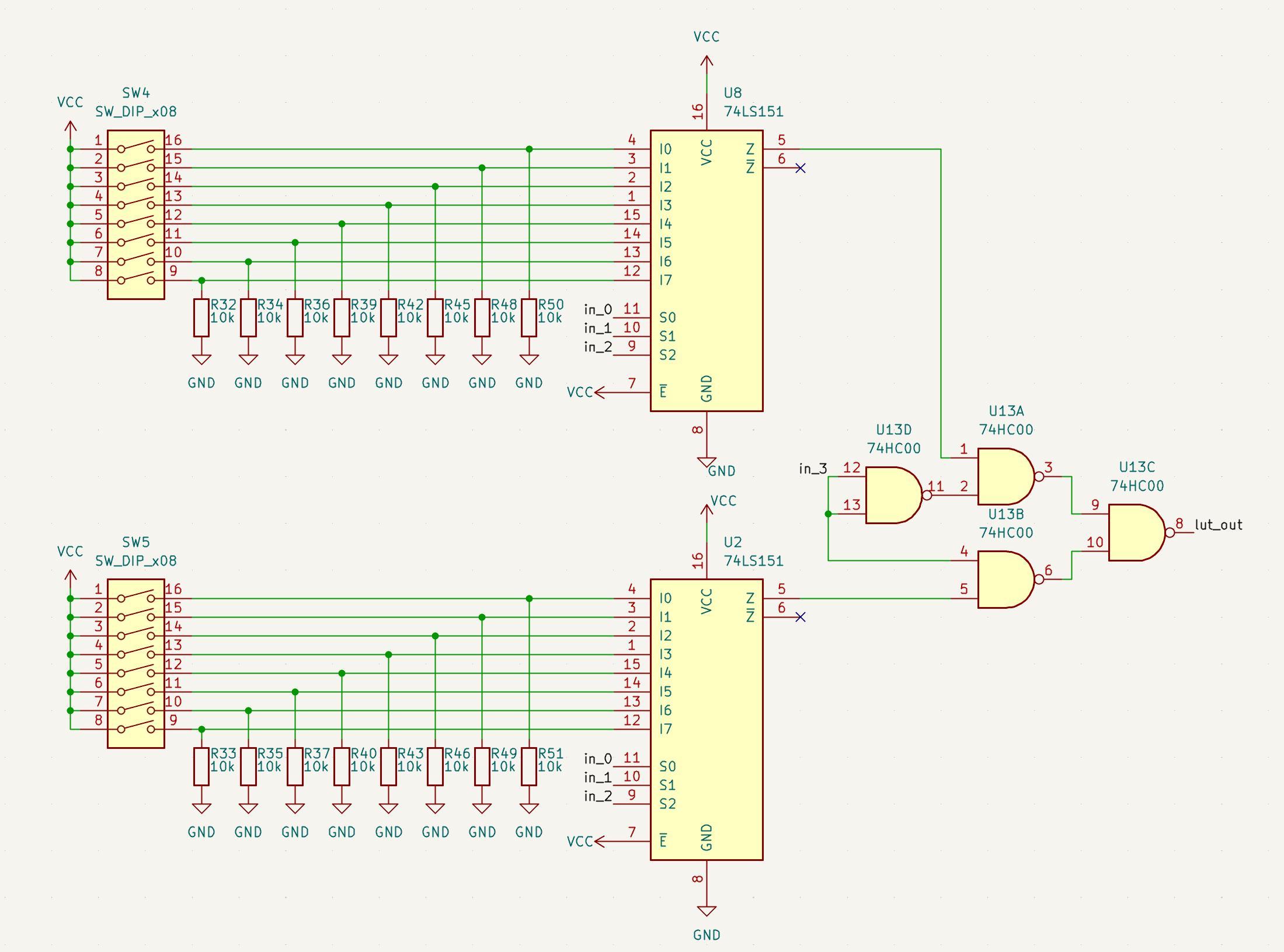
The LUT is a 16 to 1 multiplexer. It is made of two 8 to 1 multiplexers, followed by a 2 to 1 multiplexer made from 4 NAND gates, as there are no cheap widely available 16 to multiplexers. The 16 bits can be set to either 0 or 1 and then the 4 input bits are used to select which of the 16 bits are passed to the output. This allows the any logical function of 4 inputs to 1 output to be implemented.
The Flip Flop
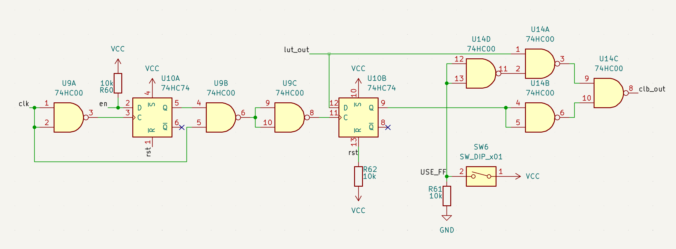
The output of the LUT is passed to a D flip flop which can store the value. The output of the CLB either comes directly from the LUT or from the the flip flop based on the configuration switches.
When in flip flop mode the clock can be enabled and disabled through a enable line. If the clock signal and enable line are ANDed together to form the clock input to the flip flop, this can result in extra edges on the clock input. To prevent this the enable signal is latched on the negative edge of the clock before being ANDed with the clock signal.